
In this page we will walk through the common issues and challenges encountered in 3D printing with a material science approach. The idea behind the page is to provide more scientific knowledge to common issues in order to easily overcome them.
To begin, it is important to understand what material is being used in 3D printing: Polymers
Polymers are large molecules, or “macromolecules”, formed by large numbers of repeating units known as “monomers” in the polymerization process. The polymerization process bonds the monomer molecules together in a chemical reaction, forming the backbone of the polymer.
The type of polymers produced can vary depending on the chemistry and composition of monomer compounds that construct them. The links created between the monomers will be defined as covalent bonds.

Polymers can be divided into 2 families: thermosets and thermoplastics.
Thermosets are polymers that are irreversibly cured from a soft solid or viscous liquid pre-polymer into a solid polymer. The curing process is also known as cross-linking, which proceeds via a chemical reaction that connects all the monomers and pre-polymers to form a network structure. A cured thermoset can no longer be melted and usually is not thermally processable.

Thermoplastics are materials which become soft when heated and hard when cooled. Thermoplastics can be heated, molded and cooled multiple times with minimal change in their chemistry or mechanical properties. Unlike thermosets where each of the polymer chain is linked to others with a covalent bond, thermoplastics have their polymer chains linked with each other with weaker links which will be defined as non-covalent bonds.
Polymers can also be divided into two main categories depending on their micro-structure:
Amorphous and Semi-Crystalline
One of the ways that different thermoplastics can be identified is through their micro- structure, which can define the properties and behavior of the polymer.
Amorphous
Amorphous polymers are identified for not having a long-range ordering. This means that the polymer chains are randomly oriented.
Generally speaking, clear plastics are often made with amorphous polymers, such as PMMA, PS and PC.

Semi-Crystalline
Semi-crystalline polymers are identified for having an ordered structure with structural domains known as “crystals”.
Crystals are an ordered and tightly packed group of polymer chains. Crystalline domains and amorphous domains co-exist in semi-crystalline polymers, thus the “semi”. The proportion of crystallized areas is defined by the degree of crystallinity. A specific characteristic of semi-crystalline polymers is that this degree of crystallinity can highly affect their mechanical and thermal properties.

Now that we have a better understanding of the material structure we will dive into its thermal properties to understand its behavior as a function of the temperature. In order to do that, we first need to define the test which will reveal the thermal properties of a polymer: DSC.
DSC definition
Differential scanning calorimetry (DSC) is a type of thermal analysis in which a specimen is placed within a chamber and the amount of heat required to continually increase the internal temperature of the chamber is measured. This form of analysis is designed to pinpoint the temperatures at which the specimen undergoes certain state transitions e.g. Glass transition, crystallization, and melting, by documenting how a polymer reacts to the gradual heat increase via its level of energy absorption and release.

Glass transition temperature (Tg)
The glass transition temperature can be found in all polymers, it refers to the temperature at which a polymers physical state transitions from glass (hard & brittle) to rubbery (soft & flexible). The Tg is usually used to highlight the highest working temperature of an amorphous polymer.
Crystallization temperature (Tc)
Crystallization happens between Tg and Tm (melting temperature). It is the process of polymer molecules aligning to form crystals. The crystallization temperature is the point at which the polymers crystalize at the highest speed.
Melting temperature (Tm)
The melting temperature is the point at which the crystalline domains of a semi- crystalline polymer starts to melt/deform. Amorphous polymers do not have a defined melting temperature.
Decomposition temperature (Td)
The decomposition temperature is the temperature at which a material begins to deteriorate, meaning that the backbone of the polymer begins to break down.
Notes about the above graph and definitions
A simple way to understand it is that the heat(energy) injected in the chamber will be used to increase the internal temperature, however if the sample (polymer) inside the chamber absorbs some thermal energy for structural realignment, more heat will be needed to be injected to continuously increase the temperature at a constant rate.
Referring to the graph below, at the beginning a constant amount of heat is applied to the system to increase the temperature at a certain rate. At Tg (glass transition temperature), we can notice that more heat is required to increase the temperature at this same rate, this is because the sample will absorb some thermal energy to break its non-covalent bonds and make the polymers move more freely (resulting in the material becoming soft).
After this phase transition, the sample will have a higher heat capacity, so the system will still require a constant amount of heat to be injected to increase the system temperature at the same rate, but this amount will be higher than before Tg. The energy continuously absorbed by the sample will make the polymer microstructure move more and more freely (excite them). At Tc (crystallization temperature), the polymer chain of the sample will have enough free movement to form crystals. The sample will then release energy (heat) which means that we need to inject less heat to the system to increase its temperature.
The reason is that the crystals structure (a more ordered structure) is coming from a more disordered structure, which will require less energy, thus the release of the extra energy. Once the crystals are formed, no more energy will be released from the sample to the system. However, soon after creating the crystals, at Tm (melting temperature), the polymer chains will continue gaining energy(movement) which will excite them too much and make them break the crystal structure, thus absorbing energy from the system, thus needing to inject more energy in the system to continue increasing the temperature at a constant rate. After breaking all the crystals, the sample will not require any additional energy from the system. This explains the two opposite spikes at Tc and Tm. At Td (decomposition temperature), the sample will start to decompose, meaning that covalent bonds will start to be broken, the sample will lose its heat capacity and thus less heat will be needed to increase the system temperature.
Now that the thermal transitions and behavior of polymers in function of the temperature are better understood, we can use this knowledge to explain some of the 3D printing phenomena:
Warping, oozing and overhangs.
Before jumping into these phenomena, we need to clarify an important point regarding printing speed and printing temperature.
Usually printing temperature is defined as the heat block temperature (in ˚C) and the printing speed will always define the print head speed when printing (in mm/s).
In this page we will refer to more useful factors for us such as the extrusion temperature and the extrusion rate:
Extrusion Temperature: The temperature at which the plastic exits the nozzle (in ˚C)
Extrusion Rate: The rate at which the plastic is extruded from the nozzle (in mm3/s)

The extrusion temperature can be increased using different factors:
Increase the printing temperature, reduce the printing speed, reduce the layer height, or increase the nozzle heated chamber length.
The extrusion rate can be decreased using different factors:
Reduce the printing speed, reduce the layer height, or reduce extrusion thickness.
Warping
In 3D printing, occasionally we will encounter a part that deforms on the printer, curls or lifts up from the bed because of what is known as warping. This is caused by the accumulation of stress created by the 3d printing process.
The origin of the internal stress is still under debate, and depending on your 3D printer configuration, many factors may be contributing to the as-built internal stress. Here is one hypothesis which should be considered for all FDM machines:
During the extrusion process the polymer is forced through a die (small hole/nozzle), and during this step the polymer chains will be stretched to a stress state, then stuck to the build plate or a previous layer of plastic. This stress will slowly be released over time, however if the temperature does not allow the polymer to freely move enough to release the stress, or if the layer is not well stuck to the bed or the build plate, the accumulation of this stress throughout the layers will force the part to macroscopically deform.

Warping and cracking is always representative of this accumulation of stress exceeding the bond between the bed or layer adhesion.
As a result, we have three ways to prevent warping/cracking:
1. Give polymers enough energy to move freely and release their internal stress.
Most of the stress release happens right after the extrusion, indeed the material will be extruded at a high temperature then cooled down below Tg. It is during this time above Tg that the polymer will release most of its internal stress, however if this time is too short, it will not have time to reach equilibrium. Increasing this time period is a way to reduce warping.
This time period can be increased with the following ways:
Increasing the extrusion temperature (PT):
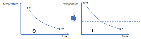
Increasing the room or chamber temperature (RT):
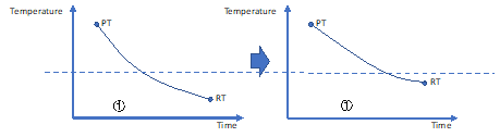
Decreasing the cooling rate:

2. Improve bed or layer adhesion
The accumulation of stress will tend to lift up the layer from another layer (delamination) or the bed (warping). However, if the bed/layer adhesion is strong enough to resist the deformation, the polymer will be able to release its stress without deforming the part. The bed adhesion can be improved by using adequate bed surfaces and coating.
Before talking about how to improve layer adhesion, let us have a look at what layer adhesion is:
Layer adhesion is possible thanks to the entanglement between polymer chains from one layer to another.
This entanglement is possible when both layers are heated up above Tg and both layers have their polymer chains moving freely, and through this movement the chains entangle with each other.
To improve the layer adhesion, we have to increase the number of entanglements between the polymer chains at the layer interface. The number of entanglements can be increased by increasing the time where both layers are in contact with each other with a temperature above Tg. As we can see this is the same solution as number 1. However, an extra factor which can improve the layer adhesion is increasing the contact surface between the layers by increasing the extrusion width.
3. Reduce stress creation
This third solution to solve warping relies on reducing the root cause of warping: internal stress.
As mentioned earlier the stress is created by forcing the material through a die which will created a velocity curve which will stretch and oriented the polymer chains. Reducing the stress creation rely on flattening this velocity profile. This velocity profile can be flattened by increasing the nozzle size, reducing the extrusion rate, decreasing material viscosity (by increasing the printing temperature) or coating the internal nozzle surface with low flow resistant surface.
The above explanation of warping can be applied to amorphous and semi-crystalline polymers. However, semi-crystalline polymers face an additional source of stress: crystallization.
Indeed, when printing, the part will undergo crystallization when cooling down creating small crystals which, as ordered structure, take less space and will force the part to shrink. This is why Nylon materials will warp even though the build plate may only be 45 degrees. If the crystals are formed too quickly, each layer will have small crystals creating a lot of stress per layers and the accumulation of this stress will macroscopically deform the part.
Oozing
In this part we will differentiate two kind of oozing depending on the root cause.
The first root cause is oozing created by the extruded filament being linked with the material inside the nozzle. The extruded filament will then force the material inside the nozzle to stretch out of the nozzle as the nozzle is moving to another location. We will rename this phenomenon as stringing (because of this string created).
Polymers with a high molecular interaction, or polymers which have absorbed moisture tend to have this issue.

A simple way to solve this stringing issue is to cut the extruded filament from the material in the nozzle by performing a wiping movement with the nozzle before moving the nozzle to another location.
The second root cause is the actual material oozing created by the residual pressure and gravity which will force the material out of the nozzle over time.
As mentioned, the above 3 factors will define the amount of material oozing out of the nozzle:
Residual pressure, gravity and time.

In order to reduce oozing, we will need to decrease or counter each of them:
Residual pressure:
Residual pressure is a result of the printer building up pressure within the nozzle to extrude at a certain volumetric speed. This pressure can never be completely discharged from the nozzle over a very short period of time and therefore the material will keep extruding slightly. To decrease the residual pressure, we can increase the retraction settings (distance, speed), increase coasting (using the residual pressure to finish the layer), decrease the extrusion rate (need less pressure to extrude) or increase the printing temperature (need less pressure to extrude).
Gravity
Gravity will always pull the filament out of the nozzle, and if the gravitational force is stronger than the flow resistance of the plastic against the nozzle’s internal surface and shear within the plastic, it will ooze out. Note that the flow resistance between the internal surface of the nozzle and the plastic can be increased by increasing the die L/D ratio (L: length of the die capillary, D: diameter of the nozzle hole). The shear within the plastic can be increased by lowering the temperature of the nozzle (thus the stand-by temperature in several dual extrusion 3D printers).
Time
The amount of material oozing from the nozzle also depends on the amount of time the nozzle is inactive. The greater the duration, the larger amount of material there is. This time can be significantly reduced by having high travel speed, acceleration and reasonably high jerk settings. The material will not have time to ooze out before reaching the other part of the model. Having a high travel speed and acceleration should not affect ghosting as it would with increasing the print speed and acceleration. However, for dual extrusion printing, this factor cannot really be changed.
Overhangs
Although it is recommended to use support for overhang angle, it usually saves time and material to being able to print high quality overhang surfaces.
The challenge when printing overhang surfaces is the amount of actual unsupported area. As you can see below the same angle can give different unsupported area depending on the layer height. It can appear that the smaller the unsupported area the better, however the smaller the layer height the less rigid the unsupported area will be. It will always be a balance between rigidity and amount of unsupported area.
Different factor can affect the overhang surfaces. As represented on the graphic below two main forces will be applied on the unsupported area: its weight (F1) and the polymer stress (F2).
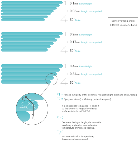
The main factors affecting theses forces is summarized above, however generally speaking the best overhang surfaces will be given with a high layer height (more rigidity), low printing speed (more consistent extrusion) and high extrusion rate (more consistent extrusion).
Before closing this section, it can be useful to also learn about the different mechanical and thermal properties which can define a polymer. These 3 tests can determine how “strong” a material is depending on the application you require from your print.
Let us first review the 3 main mechanical tests:
Tensile testing

The tensile testing is where a polymer specimen is subjected to tension until it breaks. The test can be used to determine a specimen’s tensile strength, Young’s modulus, and elongation at break.
Charpy impact test
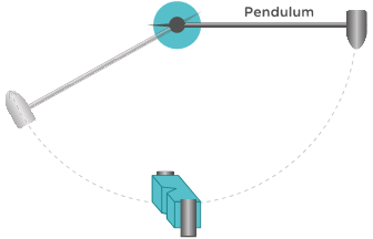
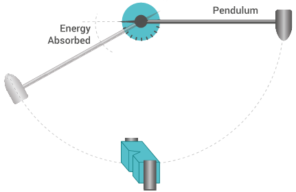
The Charpy impact test is the process of measuring the amount of energy upon impact that is required to fracture a test specimen. This test is conducted by fixing an appropriate polymer specimen in place and releasing a pendulum with a set mass at a set height to collide with the test specimen.
Three-point flexural test
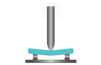
Three-point flexural test is the measurement of a specimen’s resistance to deformation under a gradual load. The test samples are subjected to significant tensile and compressive stresses in their plane in addition to shear stresses. This test can be used to determine the bending strength and bending modulus.
Each of these tests will give important data which will define the material performance:
The tensile strength will give a graph similar to the below one: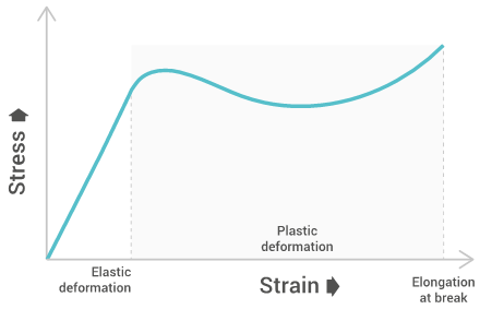
Tensile strength
Tensile strength characterizes the maximum stress required to pull the specimen to the point where it yields or breaks. Tensile strength at yield measures the stress at which a test specimen yields to stress (known as necking), tensile strength at break measures the stress at which a test specimen breaks, and the ultimate tensile strength is the maximum between both. This allows us to understand the limit of a materials strength and its behavior when under stress.
Elongation at break
Elongation at break measures the deformation ratio between initial length and increased length right before breakage. This allows us the see the amount of stretching a material can endure before breaking.
Young’s modulus
Young’s modulus measures the resistance of polymers to deformation under stress along a single axis. Young’s modulus can be used to estimate the stiffness of structures made by the material.
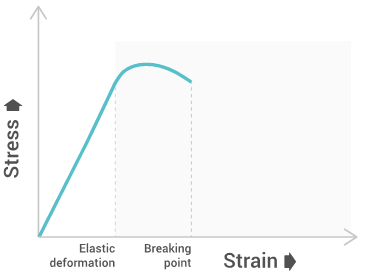
The bending strength will give a graph similar to the below one:
Bending modulus
Bending modulus is a local physical property that is computed as the ratio of stress to strain in flexural deformation. The Bending modulus has similarities to Young’s modulus as it tests the polymers ability to resist deformation.
Bending strength
Bending strength represents the highest stress experienced within the material at its point of yield or break.
Charpy impact strength
Charpy impact strength tests the amount of impact force or energy (kJ/m2) that is required to fracture the test specimen.
Now let us review the thermal properties:
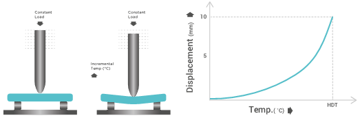
Heat deflection temperature
Heat deflection temperature is the measure of the temperature at which a polymer undergoes a certain amount of deformation. The test is conducted using a specific load, while steadily increasing the temperature by 2 °C/min and measuring the temperature once the displacement of the contact sensor of the specimen reaches 10mm.
Vicat softening temperature
Whilst comparable to HDT, the Vicat softening temperature differs by providing a testing method that simulates the point at which temperature softens the material’s physical properties enough for an external object under a set pressure to penetrate the outside surface of the specimen by 1mm.

Melt index
Melt index characterizes the flow behavior of a polymer under a set pressure and temperature. This is achieved by extruding the polymer and measuring the total weight of the extrudate in a set time-period. The more material that extrudes, the increased weight and therefore the lower viscosity.